Leaderboard
Popular Content
Showing content with the highest reputation since 07/27/2015 in all areas
-

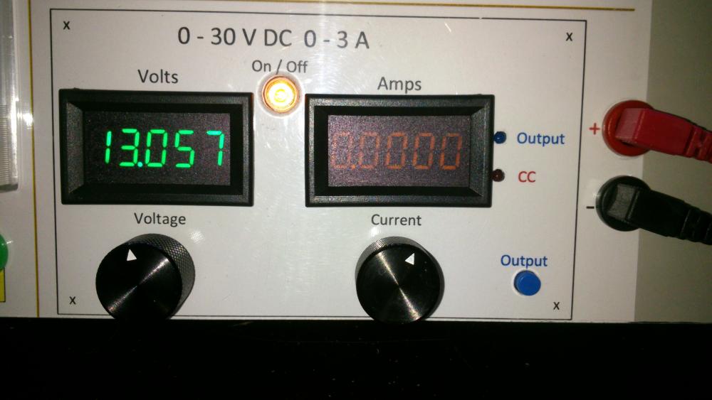
0-30V 0-3A Latest Data
AsSa and 3 others reacted to repairman2be for a topic
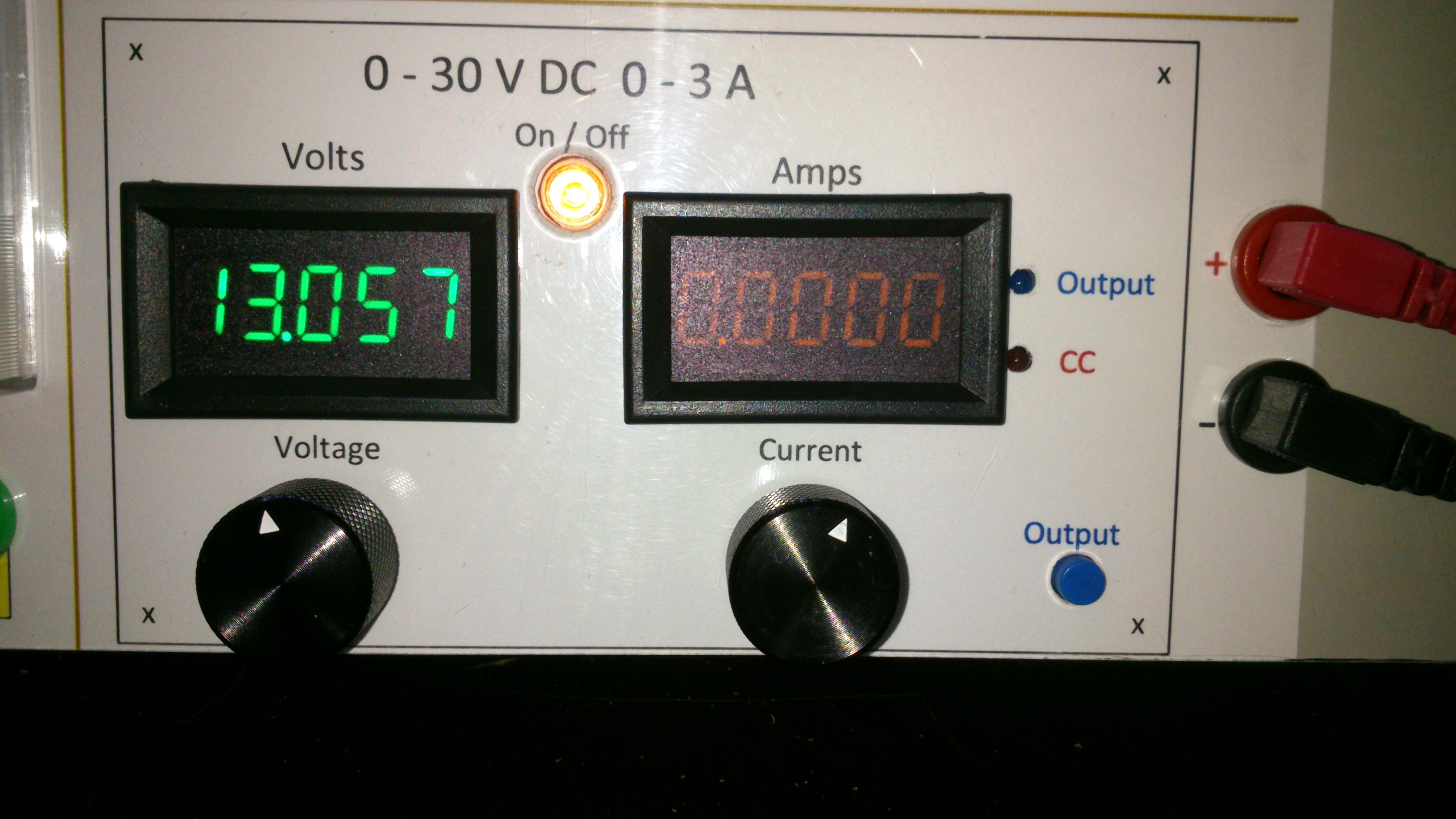
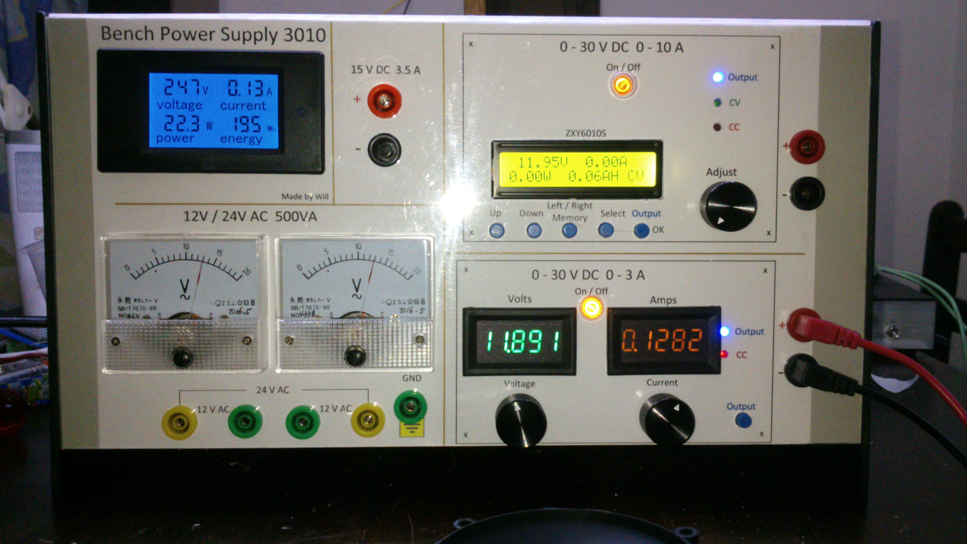
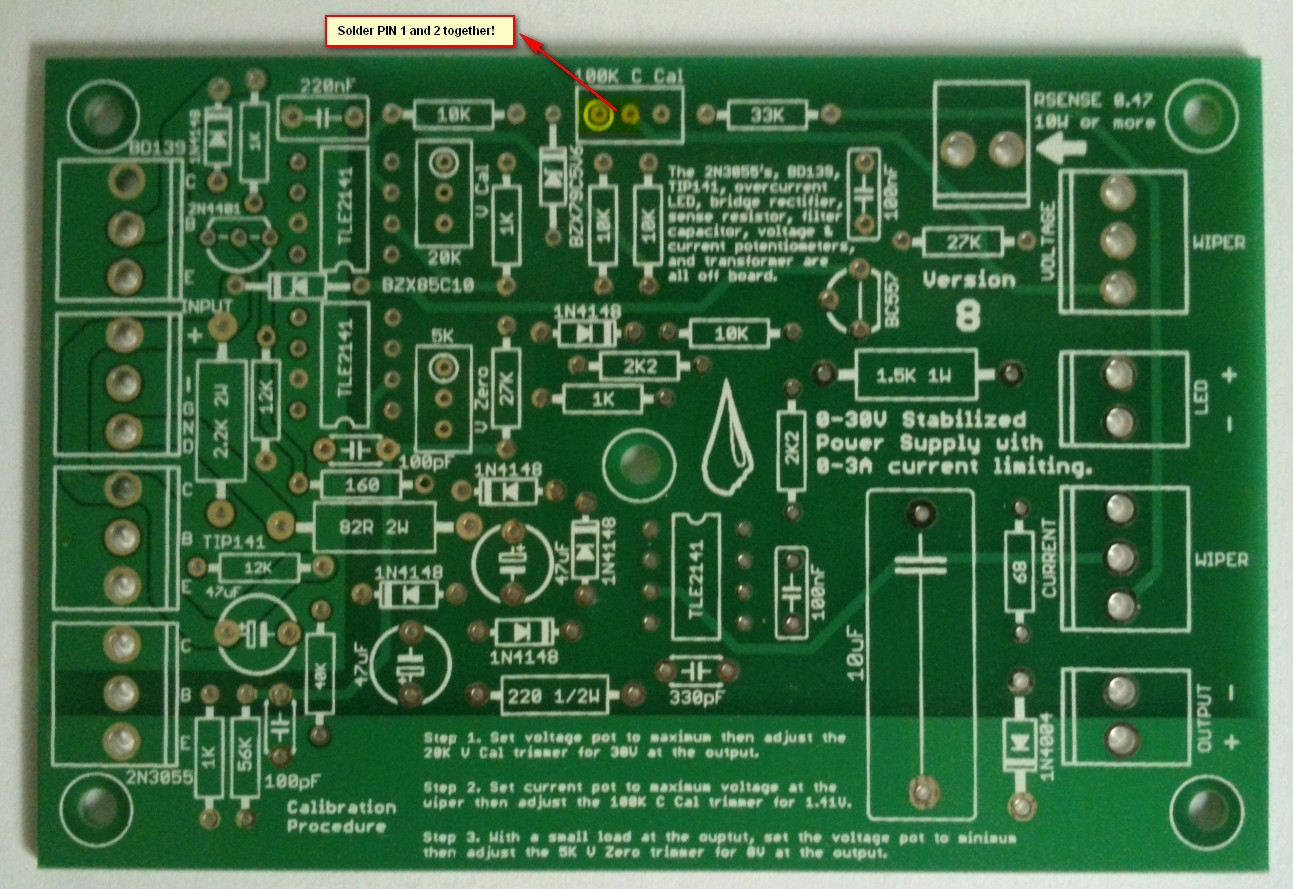
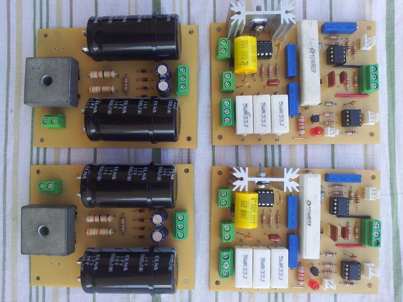
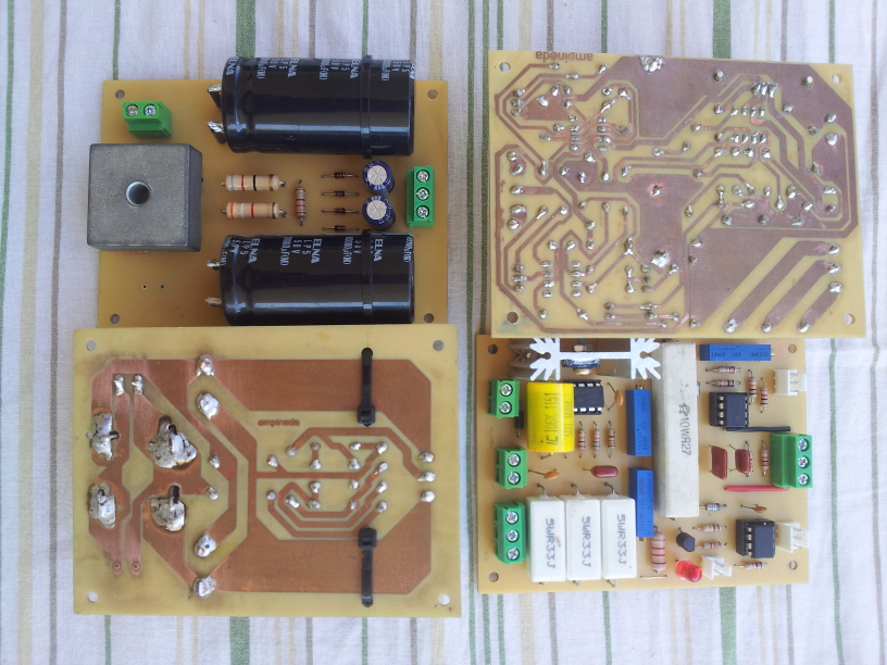
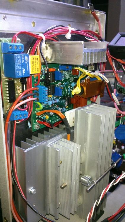
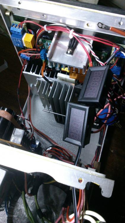
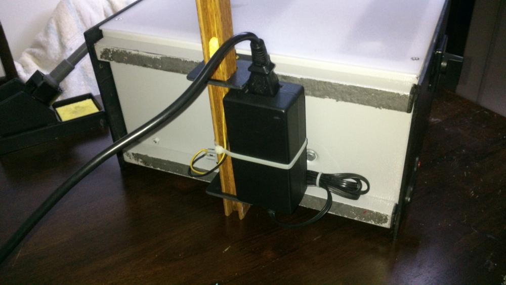
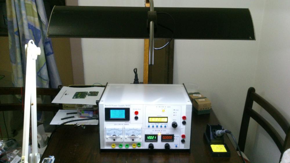
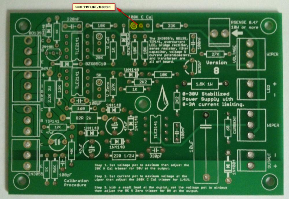
Hi all, Finally after some months have gone by, my build of the Power Supply is done. I have used liquibyte schematic Rev. 8 and had made the cirquit board according to the Gerber.zip file he posted here: 0-30V Stabilized Power Supply Page 88 posted October 6, 2014 "http://electronics-lab.com/community/index.php?/topic/29563-0-30v-stabilized-power-supply/&page=88" I left out D10 and R15 as per his description. I have plenty of boards leftover if someone has a need for it. There was only one mistake liquibyte made which have outlined in one of the pictures uploaded here. I was fortunate enough to get a big case with a Toroidal transformer from the scrapyard. Also many parts are recycled from various sources. Regards, William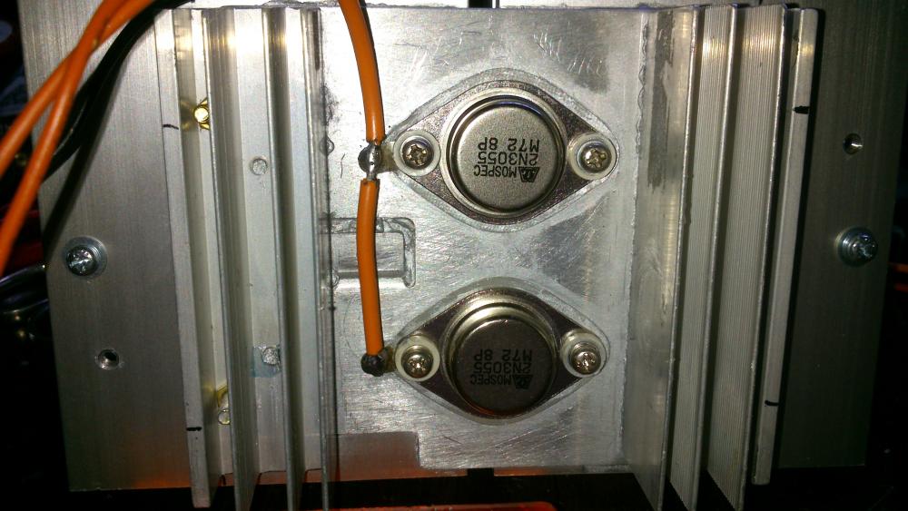

 4 points
 -
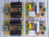
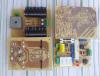
Finally, my post with the Eagle .sch and .brd, full gerbers, and parts list for Digikey in a zip file. I'm also including many of the pics I took as I was building that were posted both before and after this post. I'm still not completely done and may add more pics later. One thing I have changed is the third transformer for the auxiliary circuitry for the temperature sensor and fans and the displays (I wanted a better transformer than the Radio Shack special I had on hand). Archive attached. 30V.zip
 3 points
 -

Solar-powered Bee Hotel w/ Particle Argon (ongoing project)
Jolin He and one other reacted to JamesMVictoria for a topic
Nice one, I like it.2 points -

How to easily turn on/off all debug message on Arduino IDE
SharonWatkins and one other reacted to MrNams for a topic
But even if we disable debug, it will call print method and do not print anything. I mean we should make it something like #ifdef DEBUG Serial.print("\n debug controlled print"); #endif Here when we disable macro, its like code is not written for compiler, code will be removed in macro processing itself.2 points -

H Bridge PWM DC Motor Driver + PCB
senaka ranathunga and one other reacted to sam.moshiri for a topic
An H-Bridge (Full-Bridge) driver is quite popular in driving loads such as brushed DC motors and it is widely used in robotics and industry. The main advantages of using an H-Bridge driver are: high efficiency, rotation direction change, and braking the motor. In this article/video, I have introduced a complete H-Bridge DC motor driver using four IR3205 power MOSFETs and two IR2104 MOSFET drivers. Theoretically, the above-mentioned MOSFET can handle currents up to 80A, however, in practice we can expect to get currents up to 40A if the MOSFET temperature is kept as low as possible, using a big heatsink or even a fan. References Article: https://www.pcbway.com/blog/technology/Powerful_H_Bridge_DC_Motor_Driver.html [1]: IRF3205 Datasheet: http://www.irf.com/product-info/datasheets/data/irf3205.pdf [2]: IR2104 Datasheet: https://www.infineon.com/dgdl/Infineon-IR2104-DS-v01_00-EN.pdf?fileId=5546d462533600a4015355c7c1c31671 [3]: 1N5819 Datasheet: https://www.diodes.com/assets/Datasheets/ds23001.pdf [4]: IR2104 Schematic Symbol, PCB Footprint, 3D Model: https://componentsearchengine.com/part-view/IR2104PBF/Infineon [5]: IRF3205 Schematic Symbol, PCB Footprint, 3D Model: https://componentsearchengine.com/part-view/IRF3205ZPBF/Infineon [6]: CAD Plugins: https://www.samacsys.com/library-loader-help2 points -

Non Contact Hand Sanitizer Dispenser, Easy, Cheap, No Arduino!
sam.moshiri and one other reacted to admin for a topic
Thanks for sharing your project with us. Could you give more details on the control board?2 points -
The original circuit should work fine up to 15V at 1A if you replace the old opamps with the newer higher voltage ones. You probably should recalculate the resistors that set the maximum voltage and current outputs. If the Chinese kit uses the transistor that shorts the opamp output when the power is turned off then the resistors that feed the transistor need to be recalculated for the reduced voltage. I have used perforated stripboard for many projects including very complicated ones. The copper strips are cut to length with a drill-bit and become almost half the wiring of a pcb. The parts and a few short jumper wires become the remainder of the wiring. Only one wire is in each hole so changing a part is easy like on a pcb.2 points
-
Hi, as promised I made an English translation of my working. Maybe there is few mistakes and I am sorry for that ! Good reading. ExplicationEN.pdf2 points
-
I use copper wire, not rice wire. They put rice in everything they make, especially batteries.2 points
-

0-30 Vdc Stabilized Power Supply
electron234 and one other reacted to elctro123 for a topic
So Finally which version of schematic is correct / flawless to build the PSU ?2 points -
February 23 above on this page has the latest schematic of the revised 3A lab power supply.2 points
-
Does anyone has LM3914 pspice library? i desperately need it..pleeeeease!2 points
-

Low power solenoid?
AmelieScott and one other gave a reaction for a topic
I want to apply force for an extended amount of time (10 secs to a couple minutes) using a solenoid actuator. Unfortunately, it seems that solenoids use a lot of power when they are active. Is there a solenoid type that will only use power when switching between active and not active? There's probably a way I can do this with an external mechanism, but I was wondering if there may be commercial solenoids that have this built-in. Thanks, Jessica2 points -
Illegal content (ebook/magazines/software) will be deleted without any notice. Thanks2 points
-

Overload Protector A16 ???
joeydennis11 and one other reacted to tjolle62 for a topic
In a few circuit diagrams i have they refer to a what seems to me is a transistor with B C E as a overload protector and with number A16 and i have looked for a few hours on the net and i can't find anything on this little fellow, Anyone knows what I'm looking for and wanna share that info Please .... Come on !! 48 visits !! some one must know what it is !!! PNP is it also...........2 points -
Overload Protector A16 ???
joeydennis11 and one other reacted to tjolle62 for a topic
At last i got a theori from a totally different place and he wasn't shure either but he had a weak memory that it could be 1A16 and a PNP transistor but after several deep searches on the I-net it didn't make any kind of senses whatsoever ???2 points -

Car battery to parallel port
tracythomas50 and one other reacted to MP for a topic
When you use your resistive divider to drop the voltage down to 5 volts, you just need to select values of resistors to limit the current. This is basic ohm's law. V/R. Was this your question or did I misunderstand? I am not sure how you intend to monitor status by using one 5 volt pin. As an interface to the parallel port, you could use an LM3914. This would give you the resolution you need. There are also many other ways to proceed. You need to convert from analog to digital to read anything useful from the parallel port. MP2 points -

Car battery to parallel port
tracythomas50 and one other reacted to Omni for a topic
Hi TJBraza, http://www.analog.com/UploadedFiles/Data_Sheets/ADT7485A.pdf Although, it will probably require a small program written in C or Visual basic to convert the string MSB & LSB into a more easier read etc... Take a moment and review the data sheet, the IC has a lot of potential.2 points -

SL100 & SK100 transistor
AmelieScott and one other reacted to alanng96 for a topic
I can't find SL100 & SK100 transistor :'( Which transistors can replace these? Thank you for your help~ ;)2 points -
Calm down people. It is not Mixos's fault, if it is against the law he has to remove the content. This site is very good for asking electronic related questions, I have yet to find a better one.2 points
-

PCBGOGO after-sale service review
dorrismillerrr123 reacted to KrisDong for a topic
The board is made very precisely, it's clean and very pleasant to touch. Markings on the silkscreen layer are very good readable. Soldering does not cause trouble, tin adheres very well to soldering points with a small amount of flux. It is also worth mentioning that the PCB is very robust to desoldering. The company is very solid, although you order 10 pieces, you get at least 1 PCB more for test, prototype, present, etc. When I signed up for an account, I also got a $20 coupon for free. Excellent construction and assembly work done by PCBgogo.No problems encountered, highly recommended.1 point -
I ordered a LYG55T024FS52S motor (https://www.hurst-motors.com/lyg55geared.html), but I misread the information about the capacitor. I thought it said capacitor was supplied with the motor, but that was only for the 115 VAC motors. Since I ordered the 24V, mine did not come with a capacitor. So I’m looking to buy one. The spec sheet says I need a 20/15 mfd 50/60 Hz capacitor. This is the closest I’ve found: http://www.mcmaster.com/7245K721/ Will that work for this purpose?1 point
-

Except by doing physical projects, how can I make learning digital electronics fun?
Maria Erick reacted to HarryA for a topic
Why not read books that interest you? For example:: Digital Design and Computer Architecture1 point -
 What’up, community! Join us in this exciting journey of pushing the boundaries of technology and discovering new possibilities with Wio-WM1110 projects now! Discover more about Wio-WM1110 Module and Seeed Fusion PCBA Service The appealing new product, Seeed Studio Wio-WM1110, is the ultimate wireless module for developing low-power consumption, long-range IoT applications. Embedded with Semtech LR1110 and Nordic nRF52840, this module features Semtech’s LoRa technology for long-range wireless communication, GNSS tracking, Wi-Fi, and Bluetooth services while reducing complexity and cost. Additionally, don’t miss the magnificent function for asset tracking, inventory management, asset loss, and theft prevention. It is perfect for smart agriculture, wireless meter reading, and smart city applications. Wio-WM1110 module has been applied to SenseCAP S2120 8-in-1 LoRaWAN Weather Sensor and is widely used in smart agriculture, urban weather, etc. By capturing critical metrics such as air temperature, humidity, wind speed and direction, rainfall intensity, light intensity, UV index, and barometric pressure data and transmitting them via LoRaWAN®, the weather sensor enables you to access hyper-local weather information with ease. We are ready to illuminate and spread your ideas coupled with projects anytime! As an advocate for technology innovation and creativity, Seeed is thrilled to extend its support to the hardware community worldwide through the sponsorship of Wio-WM1110 projects. With Seeed Fusion PCB Assembly Service, everyone can explore their ideas and bring them to fruition without the hassle of sourcing and assembling components. If you have an interesting concept for Wio-WM1110 and are willing to share it with the community, share it with us and we can help you make it a reality with Seeed Fusion’s one-stop agile manufacturing capabilities. Get 2 boards fabricated and assembled completely free with Seeed Fusion’s turnkey PCB Assembly service. Meanwhile, if you have mass production requirements, we highly recommend taking advantage of the Seeed Fusion PCB Assembly service and getting the Wio-WM1110 modules. Find out more discounts below! Wio-WM1110 has been added to Seeed Open Parts Library, available for just USD$14.9! What does that mean? Like all PCBA OPL components, these parts are available for use with the Seeed Fusion PCB Assembly service at a lower price, but more importantly, these parts are stocked locally, so if all parts are sourced from the OPLs, then super fast PCB assembly can be realized from as little as 7 working days. Based on one part per PCBA. Until further notice. Can’t wait to apply? Then keep reading to discover more exciting details. One Step Closer to Wio-WM1110: Please fill out the form: click here to submit your bravo project ideas. Each person is limited to two PCBA boards 100% completely FREE for one design, including PCB fabrication, the cost of parts, assembly and shipping. The design must include Wio-WM1110. When preparing the BOM file, just add the Seeed SKU 114992865 or the part number Wio-WM1110 to your BOM file. Add the order to the cart then contact our customer support ([email protected]) to obtain the corresponding cash coupon for settlement. By participating in this event, you agree to review your experience with us and allow us to share it and the design with the community on our social media platforms (Facebook, Twitter, blog, etc.). The design does not need to be open-sourced and production files will not be shared with the public (unless you want to). We hope your experience will go on to inspire more users to embrace IoT, LoRaWAN® and its capabilities. Scale up your Wio-WM1110 Creation with Seeed Studio Co-Create Program! We will invite well-received Wio-WM1110 projects to the Seeed Studio Co-Create Program, where your products can be listed, sold and shipped directly by Seeed on the Seeed Studio Bazaar. We will also support designers to reach thousands of like-minded customers and distributors with Seeed’s global sales channels and social media presence. Don’t hesitate! It’s a great chance to show off your ideas and skills. Join forces with the Wio-WM1110 and fuel your passion for IoT1 point
 -

DIY - ARDUINO BASED CAR PARKING ASSISTANT
davidjackson reacted to Ashish Adhikari for a topic
Introduction ---------------- Hi Friends, I am back again with another Arduino based home automation project. This time I am trying to make my partner's life easy by installing a collision avoidance system in the garage to help her park the car safely without hitting the garage wall. So, in this video, I am going to use an ultrasonic sensor to calculate the car's distance from the garage wall and display it using green, yellow and red LEDs. The color of LEDs indicates whether to keep moving, slow down, stop or go back. The total cost of the project is around $20 - $25. Step 1: Logic The project has 3 phases Phase 1: Waiting for the car In this phase the device keeps looking for a moving object within the sensors proximity. If an object enters the proximity then one of the three LEDs turns on based on how far the moving object is. If the object is way too close, then a noise is made to make the moving object aware of the distance. Phase 2: No car in the garage If there is no object in the proximity then turn off all the LEDs. Phase 3: The car has stopped moving (Parked in the right spot) If the object has stopped moving and is still in the proximity wait for 20 CPU cycles and then turn off the LEDs. Step 2: Hardware Requirement For this very simple project we need: - A Perfboard - An Arduino nano/uno (whatever is handy) - A Red, Green and a Yellow LED (Light Emitting Diode) - 3 x 220ohm resistor for the LEDs - One HC-SRO4 Ultrasonic Sensor - A Buzzer shield or A buzzer and a 100 ohm resistor - A 220v AC to 5v DC Buck step-down module - One Female Pin Header Strip - An Ethernet cable - Some connecting cables - A USB cable to upload the code to the Arduino - and general soldering equipments Step 3: Assembly Let start by connecting the LEDs to the board. Connect the Red LED to pin D2, Yellow LED to D3 and the Green LED to D4 of the Arduino by putting in a 220ohm resistor between the Arduino board and the LEDs. Now lets connect the Buzzer to analogue pin A0. Next, connect the Trig pin of the Ultrasonic Sensor to D5 and the Echo pin to D6 of the Arduino. Once all the modules are connected to the Arduino board, its time for us to connect all the positive and negative pins together. Connect all the positive pins of the modules to the +5v supplied by the Buck Step-Down Module and the negative pins to the -ve terminal of the Module. That's it, we can now upload our sketch to the board. In this assembly I am using 3 LEDs to display the distance, however you can replace the 3 LEDs with a RGB LED, or you can also use an array of LEDs like an audio level indicator to display the movement of the car. Step 4: My Setup OK now lets see what I have made. I have installed the Arduino, buzzer, the ultrasonic sensor and the three 220 ohms resistors on one Perfboard. The 3 LEDs and the power module is installed on a second Perfboard. I will be covering the LEDs with a translucent cover to give it a nice look. The 220v power supply will be connected to the screw terminal block. The base unit will then be connected to the LEDs and the power supply with an Ethernet cable. Step 5: The Code int trigPin = PD5; // Sensor Trip pin connected to Arduino pin D5 int echoPin = PD6; // Sensor Echo pin connected to Arduino pin D6 int redLED = PD2; // Red LED connected to pin D2 int yellowLED = PD3; // Yellow LED connected to pin D3 int greenLED = PD4; // Green LED connected to pin D4 int buzzer = A0; // Buzzer connected to Analogue pin A0 long TempDistance = 0; // A variable to store the temporary distance int counter = 0; // Counter value to check if the object has stopped moving void setup() { Serial.begin(9600); pinMode(trigPin, OUTPUT); pinMode(echoPin, INPUT); pinMode(redLED, OUTPUT); pinMode(greenLED, OUTPUT); pinMode(yellowLED, OUTPUT); pinMode(buzzer, OUTPUT); } void loop() { long duration, Distance; digitalWrite(trigPin, LOW); delayMicroseconds(2); digitalWrite(trigPin, HIGH); delayMicroseconds(10); digitalWrite(trigPin, LOW); duration = pulseIn(echoPin, HIGH); Distance = (duration/2) / 74; // Distance in Inches if(counter < 20){ // Do the rest if the car is still moving if (Distance > 200) { // Nothing in the garrage turnThemAllOff(); } if ((Distance > 55) && (Distance <= 200)) { // Turn on Green LED digitalWrite(greenLED, HIGH); digitalWrite(yellowLED, LOW); digitalWrite(redLED, LOW); noTone(buzzer); } if ((Distance > 15) && (Distance <= 55)) { // Turn on Yellow LED digitalWrite(yellowLED, HIGH); digitalWrite(redLED, LOW); digitalWrite(greenLED,LOW); noTone(buzzer); } if (Distance <= 15) { // Turn on Red LED digitalWrite(redLED, HIGH); digitalWrite(greenLED,LOW); digitalWrite(yellowLED, LOW); noTone(buzzer); } if (Distance < 8) { // Item is way to close - start the buzzer tone(buzzer, 500); } } if ((Distance == TempDistance) || ((Distance+1) == TempDistance) || ((Distance-1) == TempDistance)){ if(counter >= 20){ // Turn off the lights if the object hasn't moved for 20 cycles (no change in distance) Serial.println("No movement detected, turning off the lights"); turnThemAllOff(); } else { counter++; } } else { counter = 0; // Reset counter if there is a movement } TempDistance = Distance; Serial.print(Distance); Serial.println(" inches"); Serial.print("Counter : "); Serial.println(counter); delay(500); } // Function to turn the LEDs off void turnThemAllOff(){ digitalWrite(redLED, LOW); digitalWrite(greenLED,LOW); digitalWrite(yellowLED, LOW); noTone(buzzer); } Start the code by defining the constants and the global variables that will be used throughout the code. Then define the pin modes in the setup section of the code. Then create a function to turn off all the LEDs and the buzzer. Now, calculate the "Distance" in inches by reading the values received from the Ultrasonic Sensor. Then by checking the value of the "Distance" we will turn on and off the LEDs based on how far the object is. If the distance is greater than 200 then turn off all the LEDs and the buzzer as the object is out of range. Else if it is between 55 and 200 then turn on the green LED. If the object is between 15 and 55 then turn on the yellow LED, and if the object goes closer than 15 inches then turn on the red LED until it reaches 8 inches. When the distance becomes less than 8 start the buzzer along with the red LED. Next bit of the code is to set the value of the counter based on the cars movement which then decides when to turn off the LEDs. It compares the value of "Distance" with the "TempDistance" and if the values are same (object hasn't moved) then increments the counter. If the object moves any-time during this process the counter is reset to 0. Finally the "TempDistance" is set to the value of "Distance". Just before comparing the Distances we also need to check if the counter value has exceed 20. I am doing this to stop the below code from executing if the car is in a steady position. Lastly we just need to add a small delay to our sketch to pause the code for a while. Step 6: Quick Demo So this is how I have installed the unit in my garage. As I walk close to the sensor the light changes from green to yellow to red and ultimately the buzzer goes on when I am too close to the sensor. In my case I have installed the buzzer next to the Arduino however I will recommend you to install the buzzer along with the LEDs. If you want you can also flash the red LED when the buzzer goes on. So now, my partner can park the car easily without making any assumptions. Doesn't matter how many times she fail her driving test she is not going to break my wall (even when she is drunk). Not that I am asking her to drive when she is drunk (just kidding). Thanks again for watching this video! I hope it helps you. If you want to support me, you can subscribe to my channel and watch my other videos. Thanks, ca again in my next video.1 point -

Touchless Covid Free Electronic Dice Using Arduino
Ashish Adhikari reacted to charlesmox1 for a topic
I'm looking forward to the next post)Keep it up!1 point -

Good book for beginners?
tommyhanks2 reacted to ernander123 for a topic
what else is there?1 point -
I am working with CS5484 for a project and I am unable to configure the IC
Conor Torres reacted to HarryA for a topic
There is a library file ( GOLANG library for SPI ) here that maybe helpful? https://github.com/stamp/CS5484 I have problems finding the page that has the {code} button to download the file; you may have to dork around with the URL a bit.1 point -

Question electrolytic capacitor
17669 reacted to nogueiraat for a topic
my room the temperature varies 31-33º the humidity varies 55-70% this epcos information valid for other electrolytic capacitor manufacturers? in the 1990s were electrolytic capacitors or another type of capacitor used?1 point -
Desktop Pick and Place Machines
Zahid Gul Khan reacted to HarryA for a topic
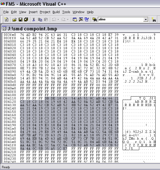
There is information here on Visual Servoing that maybe helpful; particularly the numerous references at the end of the article. https://en.wikipedia.org/wiki/Visual_servoing If you look at a bmp file of a smd image like this one (I could not find an image of the bottom of a smd). You can see the white background as FF FF FF and one scan line across the component highlighted. So in theory one could find the four corners and calculated the rotation and any x y offset. In bmp files the image is inverted. If you only need the rotation then only part of one edge would be required to calculate it I believe. smd compoint.bmp
 1 point
 -
This is a question always been asked so I try to make this list to cover as many pcb manufacturers as I can. This is a listing of websites making PCBs and also may including PCBAs. I will try to update the infomation now and then. http://www.pcbway.com/ -$5!!! http://www.pcbgeek.com/ http://www.sfcircuits.com http://expresspcb.com/ http://www.apcircuits.com/ http://www.10pcb.com/ http://www.goldphoenixpcb.com/ http://batchpcb.com/index.php/Products http://www.pad2pad.com/index.html http://www.pcbcart.com./ http://www.4pcb.com/ http://www.pcbfinpo.com/ http://www.sunstone.com/ http://www.pmsnewzealand.com/ http://www.ezpcb.com/ezpcbweb3/index.php http://dorkbotpdx.org/wiki/pcb_order http://pcbconnect.com/index.html http://www.screamingcircuits.com/Order/ http://www.pcborder.com/site_new/default.asp http://www.custompcb.com/ http://www.multi-circuit-boards.eu/?gclid=CK20v5fFga4CFYZN3godg1in6Q http://iteadstudio.com/store/index.php?cPath=19_20 https://www.itead.cc/open-pcb/pcb-prototyping.html http://www.seeedstudio.com/depot/fusion-pcb-service-p-835.html?cPath=185 http://imall.iteadstudio.com/open-pcb/pcb-prototyping.html?p=2&price=-100 - $0.2 !!! https://ecommerce.pcbfabexpress.com/ http://www.goldphoenixpcb.com/ http://oshpark.com https://www.protoexpress.com/ - SierraCircuits http://www.4pcbassembly.com/ http://www.mitchelectronics.co.uk/ http://www.customcircuitboards.com/ http://dirtypcbs.com/ http://www.elecrow.com/special-offer-for-2-layer-1010cm-max-green-pcb-510pcs-p-761.html http://pcbshopper.com/ http://smart-prototyping.com/PCB-Prototyping.html http://www.technotronix.us/ http://www.pcbunlimited.com/ http://store3.sure-electronics.com/ The list is not in any priority. I've never ordered board from any houses. I've just made board with the first two entries. This is a "work in progress". New board houses may be added, along with some comments.1 point
-
I cannot see which connects to what. Can you provide a schematic?1 point
-
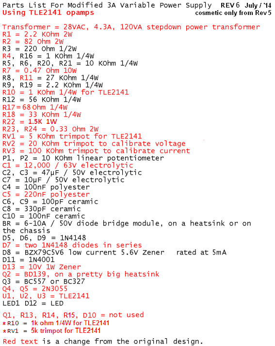
The 24VAC transformer has an output voltage too low for this power supply to produce 30VDC at 3A. The regulation will fail and there will be lots of ripple in the output at and above about 25V at 3A. I recommended a 28VAC or 30VAC transformer and higher voltage opamps years ago. For an output up to 5A then the transformer max output current should be 7A or more, the main filter capacitor C1 value should be about 17000uF or more, there should be 3 output transistors each with its own emitter resistor, a larger heatsink for the output transistors and change the value of R7 from 0.47 ohms to 0.27 ohms. I finished making improvements on this project in July, 2014 but others have made more changes.1 point
-
The original defective circuit had many overloaded parts that will blow up. The improved version fixes it. Opamp U3 senses the output current in R7 and reduces the output voltage and output current to match the current set with P2. The maximum output current is 3.0A in the improved circuit and the two output transistors have a total maximum current rating of 30A so they will not blow up with only 3.0A.1 point
-

BGA rework Process?
hunghoang reacted to soldertools1 for a topic
Hey, I also found a training institute and an article about BGA Rework Process. Follow the given link below to get a clear understanding of reworking BGA process: http://www.solder.net/services/bga-rework-services/1 point -

acid_circuit
soldertools1 reacted to audioguru for a topic
Why are you using an old fashioned vented lead-acid battery? Most circuits today are powered by rechargeable Ni-MH or Lithium batteries that have no acid.1 point -

New Proteus Libraries for Engineering Students
PalGreen reacted to CarlWilson for a topic
Thanks for the resources!!! I am currently working on the project "Electronic circuits of information collection and processing systems". The topic is very interesting, since I need to investigate the development of the linearizer of the first sensor with smooth and piecewise-linear approximation. It is also necessary to determine the value of the DC component extraction device from the signal of the second sensor. In addition to your recommended resources, I also used the writingcheap.com service, which helped me with the theoretical part of my work of developing an analog-to-digital converter. Using the information of this site http://www.analog.com/en/products/analog-to-digital-converters.html I was able to summarize the results of my research. You have an extremely helpful channel for students on YouTube. You have an extremely helpful channel for students on YouTube.1 point -
Since it was years ago I do not remember which page of which thread has version 6 or 7. I have the schematic and parts list of version 6 here:
 1 point
 -

Help Under standing Schematic PSU
Islam Amer reacted to Fliptron for a topic
Hi Islam, I'm a new user here (just signed up to answer your question), so I hope this helps. There seems to be several things that need to be understood about the overall topology of this PSU to get to answering your questions The power supply has two main parts: 1) The control section with the GHI outputs from the transformer, generates +12, -6, and -15. The ground of the control section (center point, more or less) is connected to the Positive side of the output. See ground below C4, and on the far right of the page (has the number 15 near by). (I think these numbers scattered through the schematic are test point numbers). So all of the control circuitry (anything using +12, -6 and -15) Is referenced to this ground. What is a little surprising, is that means that as the power supply output goes up/down, the control ground is doing the same. Also on this signal, is one end of the each of the six Load-Balance/Current-Sense resistors (6 x 0.36 Ohms). 2) The second part is the power section, which includes the lower half of the transformer (ABCDEF), the relays that select between the 4 voltages you listed (15-20-30-50), the bridge rectifier D7..10. The Negative side of the bridge is directly connected to the negative side of the output. (the line at the bottom of the page with label 14.) The Positive side of this bridge rectifier goes to the 6 collectors of the 2N3055s, then the 6 resistors mentioned above, then to the Positive side of the output, which as described above is also the ground of the control electronics. Since the maximum current is 3 Amps, and it will be shared evenly between the 6 resistors (with very minor differences depending on the exact characteristics of the six 2N3055s), the maximum current for each resistor is 0.5 Amp. So the max voltage across these resistors is 0.18 Volts , which gives about 90 mW , so these resistors are grossly over-sized at 5W, and will run cold (unless they are mounted on the heatsink). This also means the voltage on the 6 emitters is 0.00 to 0.18, which is averaged by the six 100 Ohm resistors and then sensed by U2 which implements the current limit circuit. U3 implements voltage control, follow pin 2 to the right which goes to the ground symbol, which we have established is power supply's positive output, and pin 3 which is connected to a voltage divider (including the front panel control) which connects to the negative side of the power supply, marked with the label 14. So now to get to your question. Regardless of what the output voltage is, the six emitters are no more than 0.18 volts above the ground of the control circuits, which tracks the positive output of the supply. The bases of these transistors will be 0.6 to maybe 0.75 volts above that. So the base voltage is always in range of the control circuit driving it. For the same reason, the 2.5V reference is an offset from the control section ground, and the power section's positive output. Yes, the six resistors also carry the base current, but this is minimal, compared to the collector current, due to the gain of the transistors. At DC, 25 deg C, and collector current of 0.5 Amps, the gain is over 100. I just did a Science (see picture below) to make sure I wasn't lying: With 15 volts on the collector, I got the following results: Vbe Ib Ic Volts mA mA 0.5 .05 3 0.56 .15 22 0.6 .36 82 0.61 .5 122 0.63 .7 190 0.65 1.0 280 0.67 1.26 370 0.7 2.2 600 (Note, Vbe is using the voltmeter in the PSU, which is not very accurate, and the transistor heated up on the last few measurements, and needed to be cooled) Anyway, the measurements I made show a gain on my test 2N3055 of about 300 when the collector current is around 0.5 amps which is the high end of what is expected in this power supply, and would contribute about 0.3% of the emitter current. Thinking a bit further, it doesn't really matter since it is sensed along with the collector current, and it all goes out through the positive output of the supply. Cheers 1 point
 -

12v lamp Dimmer lamp ideas?
Jordan&tiffany reacted to stuee for a topic
I have a 12v transformer for interior lights and a few lights for it, but want to make it a dimmer light. the working amps are 250mA. I would like to know how to wire up these three ways, so i can try each one and see if its any good and use the best.... Touch lamp. touch the metal to turn on dimmest. press again for brighter and again for brighter and again for off. Manual pot adjuster. and digital potentimeter. press up to turn up and make brighter and down for darker / off, and a reset button to turn instant off. Any help and sche... will be helpfull. Thanks in advance1 point -
How to find electronic parts?
teprojects1 reacted to audioguru for a topic
I buy electronic parts from Digikey and Newark because they have offices and warehouses in my country and they stock everything. What can't you find?1 point -

555 dc motor controller
FranceRouze reacted to Hero999 for a topic
A schematic would help us to answer the question. I wouldn't recommend either. A MOSFET would probably be better.1 point -

Sensor alarm and transmitter
Jacquelyn Norris reacted to steve10101 for a topic
Hiya, I now cant find the projects I found yesterday sorry... but the below link is a device similar to what I'm looking for, but I'm looking to make this work in reverse (hoping this may help). The distance I'm trying to achieve would be for the alarm to activate if transmitter was anything from 0-10 feet away. http://www.pimall.com/nais/rdiftagalert.html1 point -

Power conversion
Cory D reacted to Bob Wettermann for a topic
"A solar charging system is not complete without an appropriate charge controller. Most units include a charge controller to charge 12-volt lead acid batteries and inverter for drawing power. Charge controllers are also available for lithium-ion to charge 10.8V packs (3 sells in series)."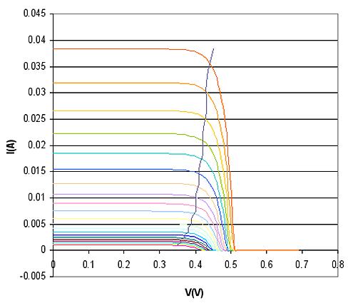 1 point
 -
Thanks for the freelancing job recommendation but I am a 70 years old government worker (I am retired with a government pension and some stocks and bonds) so I do not need more income. I do whatever I want whenever I want.1 point
-
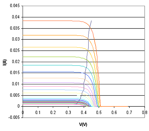
Arklite take a look at this PS output at start up using current control.1 point
-
0-30V 0-3A Latest Data
navidmomeni gave a reaction for a topic
Continued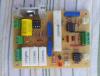
 1 point
 -

Electronic Gun !!!!!!!!!
Jordan&tiffany reacted to Silent Jack for a topic
[i would not encourage children to develop high tech weaponry and would firmly discourage them from using them on themselves or others.] I saw a project online once that took a page from the XREF taser shotgun rounds, concept. It used pressurized air to propel a charged disposable camera capacitor, prongs first out of a simple barrel. Interesting concept, though from what I read, the 330V would be far to little to achieve the taser effect. That and I understand a specific waveform is needed to affect strictly skeletal muscle and not cardiac muscle. Seems like a safety concern to me.1 point -

An excellent electronics manual
Jordan&tiffany reacted to grsparks for a topic
After running across this at the public library in town, I just had to order my own copy: "Practical Electronics for Inventors" by Paul Scherz It covers just about everything from DC to Microcontrollers and is well illustrated.1 point -
Think of the commas as periods or the periods as commas. These are used differently in different continents. It means the same. MP1 point