All Activity
- Yesterday
-
 Cornelia Reeves joined the community
 -
A casual chat with a friend got me curious about exploring online platforms, and that’s how I found 1win indonesia. The site immediately impressed me with its straightforward layout and ease of use. What stood out the most were the bonuses—they make the whole experience a lot more engaging. Signing up was quick, and I’ve been exploring its features ever since. Definitely a platform worth checking out!
-
 alexseenx joined the community
 -
 OMER Amen changed their profile photo
 -
 Chelladurai Chellam joined the community
 -
 riverhillsbuilder changed their profile photo
 -
riverhillsbuilder joined the community
-
 cubiczirconiagem changed their profile photo
 -
 Divisa Prajapati changed their profile photo
 -
cubiczirconiagem joined the community
-
 kandmconstruction changed their profile photo
 -
 Oleg Novast changed their profile photo
 -
kandmconstruction joined the community
-
 vancouver-cdneldercare changed their profile photo
 -
vancouver-cdneldercare joined the community
-
 tricities-cdneldercare changed their profile photo
 -
 Diante Desaulniers changed their profile photo
 -
tricities-cdneldercare joined the community
- Last week
-
 Do my Assingnments joined the community
 -
 Next generation Martial arts llc joined the community
 -
 TruDeliver changed their profile photo
 -
 Humidifiers add moisture to the air. They can help people with dry skin, allergies, and respiratory problems. They may also help in preventing influenza and reduce snoring. I bought this AU$2 USB Mini Humidifier DIY Kit from AliExpress and went ahead and created a cute little 3D container for it. In this tutorial, I will show you guys how I designed and assembled the humidifier circuit into the 3D model. 3D Model While browsing the Internet, I found this cute little candle holder created by SERV3D on Cults3D.com. The design was very cute and I went ahead and upsized and customized the design to fit all my electronics bits into it. With the help of Microsoft 3D Builder, I modified the 3D Model. The model has 2 compartments. The top compartment is completely hollow to hold water in it. I kept the top section open to fill water into it. All the electronics bits will go inside the second compartment. Those two screw holes are to hold the rechargeable 18650 battery holder. This pipe like structure is for the wires to go from the top section to the bottom section. The top compartment is 9.5cm x 4.5cm. So, if we calculate the volume of the cylinder it comes out to 604cm-cube. By dividing the volume by 1000 we can get the volume of water that can be stored inside that compartment. So, it comes out roughly around 0.6 liters. At the back of the model, I created a grove to fit in a block of plastic that will house the TP4056 18650 battery charging module and a SPDT switch. The charging module gets super hot while charging, so I have given enough space in the block to keep the module cool. The bottom lid will cover and hide all the electronics bits into it. The top lid has a hole in the middle to house the humidifier straw. Thats it as simple as that. 3D Printing Once the 3D model was sorted, it was time for me to fire up my 3D printing oven and start printing these 3D models. As we all know, 3D printing is the process that uses computer-aided design or CAD, to create objects layer by layer. 3D printing is not a new technology, its been there since the 1980's, when Charles W. Hull invented the process and created the first 3D-printed part. Since then, the field of 3D printing has grown exponentially and holds countless possibilities. The 3D printing process fascinates me a lot and I sometimes love to sit near my printer and watch these layers getting printed. 3D Printing is a highly addictive hobby! There are so many things you can do using a 3D printer. From designing 3D Models to printing them using the 3D printer has now become my new hobby. I've been a "maker" since I was 10 years old, and have always constructed and made my own stuff. 3D printing for me is a blessing. I am totally lost in the 3D printing heaven. 3D printing has changed my electronics workshop life forever. Before when I used to order parts, I always used to wonder if the parts would fit into my project's resources... but after I got my 3D printer... it doesn't matter at all, because if it doesn't fit - I could design and print it myself. The 3D printer was definitely "The Missing Piece" from my electronics workshop. The entire printing process took roughly around 20hrs. After extracting all the 3D printed bits, I sanded them to give them a nice and smooth texture. This is the bottom cover, that's the top lid with a hole for the humidifier straw and a handle to open and close the lid. This block will hold the battery charger and the SPDT switch into it. The main body has the top compartment for holding water in it and the bottom compartment for housing all the electronics bits into it. Schematic The circuit is very simple. By connecting an USB Type-C charging cable to the TP4056 Module we charge the 18650 battery connected to the B+ and B- terminals of the module. The humidifier module connects to the OUT+ and OUT- terminals of the charging module via a SPDT switch. Using this switch we can turn on or off the humidifier. So, these are the components that were in the DIY Kit. A circular atomizer, two plastic holders, a straw and the main humidifier circuit board. I customized the board by adding a couple of male pin headers to power this unit using a battery and dropped a blob of solder to bypass the push button switch. To assemble, insert the atomizer into the black plastic holders along with the humidifier straw. Then connect the atomizer to the humidifier circuit board. In my project the circular atomizer will be way far from the circuit board. So, I will replace the short red and black cable with a long ribbon cable. Assembling The Bottom Let's start by soldering the battery holder to the B+ and B- terminals of the charging module. Then, let's solder the -ve connector that will power the humidifier to the OUT- terminal of the board. After that, let's solder a loose cable to the OUT+ terminal. Now, let's slide the humidifiers +ve connector and the other end of the loose cable into the plastic block. Then, solder these two cables to the SPDT switch and superglue it to the block. Then push the charging module into the groves of the plastic block. Once the block is all set, push it into the back of the main unit. After that, using a couple of screws attach the battery holder to the bottom of the unit. I used hot glue to stick the humidifier circuit to the bottom of the unit. Once everything is in place, plug in the 18650 battery to the battery holder and push the white and black atomizers cable through the pipe like structure. After that, connect the atomizer's power chord to the humidifier and seal the bottom lid. Assembling The Top Be very careful while assembling the top. The atomizer has two sides. The one with more exposed metal area, touches the humidifiers straw. I soldered the atomizer to the white and black cable after passing it through the top lids hole. Then it was just a matter of putting the atomizer inside the two black holders along with the straw and then snap-closing it and pushing the setup through the hole. That's it, all done. Coloring I wasn't very confident about PLA being waterproof and not absorbing water leading to swelling and degrading of the biodegradable plastic. So, I went ahead and painted the inner bit with "Bitumen Waterproofing Membrane". Then, using Acrylic Colors, I painted the body of the 3D printed model. I gave the model a bit rustic look, but hey.. it totally depends on you how you want your project to look like. Final Demo To fill the container with water, you just need to lift the top lid and pour water into it. Once fully charged, the unit can run seamlessly for roughly around 10 hours. So, this is how my final setup looks like. Do comment and let me know if there are any scopes of improvement. Advantages Dry air causes moisture to evaporate from the skin and respiratory symptoms to worsen over time. Adding moisture to the air with a humidifier can counteract these problems. Humidifiers can help people who experience: cracked lips dry skin irritated eyes dryness in the throat or airways frequent coughs bloody noses allergies sinus headaches Disadvantages Dirty humidifiers : If the unit’s water tank is dirty, the vapor a person breathes will also be dirty. Too much humidity : excessive level of humidity can make breathing difficult and some allergy symptoms worse. Using hard water or tap water : Minerals from hard tap water can build up in the machine, causing it to wear down faster than expected. The humidifier can also push these minerals into the air, and a person may inhale them. Thanks Thanks again for checking my post. I hope it helps you. If you want to support me subscribe to my YouTube Channel: https://www.youtube.com/user/tarantula3 Video: View Full Blog Post: View References GitHub: View Stl Files: Download Wallpapers: Download Support My Work BTC: 1Hrr83W2zu2hmDcmYqZMhgPQ71oLj5b7v5 LTC: LPh69qxUqaHKYuFPJVJsNQjpBHWK7hZ9TZ DOGE: DEU2Wz3TK95119HMNZv2kpU7PkWbGNs9K3 ETH: 0xD64fb51C74E0206cB6702aB922C765c68B97dCD4 BAT: 0x9D9E77cA360b53cD89cc01dC37A5314C0113FFc3 LBC: bZ8ANEJFsd2MNFfpoxBhtFNPboh7PmD7M2 COS: bnb136ns6lfw4zs5hg4n85vdthaad7hq5m4gtkgf23 Memo: 572187879 BNB: 0xD64fb51C74E0206cB6702aB922C765c68B97dCD4 POL: 0xD64fb51C74E0206cB6702aB922C765c68B97dCD4 Thanks, ca again in my next tutorial.
 -
Given two gaps in series both gaps would have to fire simultaneously. Say the narrow gap fired first; where would the electrons come from? What do you mean by not regular needed milliseconds? I built a CDI for a chainsaw. At 1800 rpm it worked fine, at 3600 rpm it would blow the 10 ampere fuse in the 12v to 350v up-converter. I solved the problem by buying a new chainsaw 😉
-
STM32F407VET6开发板 介绍 STM32F407VET6是意法半导体STM32F4系列微控制器中的一款芯片,基于高性能ARM Cortex-M4处理器内核,主频高达168MHz,广泛应用于工业控制、消费电子、物联网设备等需要高性能和丰富外设的嵌入式系统。 1. 核心功能 CPU核心:ARM Cortex-M4 32位RISC处理器,支持DSP指令集,集成单精度浮点单元(FPU),加速浮点计算。 主频:高达168MHz工作频率。 Flash容量:512 KB片上Flash存储器,用于存储程序代码。 SRAM:112 KB 片上 SRAM,分为 3 个块(2×64 KB 和 1×16 KB)。 2. 外设和接口 STM32F407VET6具有丰富的外设和接口,适用于各种应用场景: GPIO:144 个引脚中的 82 个可用于通用 I/O(GPIO)。 ADC:3个12位ADC,最多可连接24个通道。 DAC:2个12位DAC,适合模拟信号生成。 定时器:14个通用定时器及高级定时器,支持PWM、捕获比较功能等。 通讯接口: 3个SPI接口 4 个 I2C 接口 3 个 USART 和 2 个 UART 2个CAN总线接口 1个USB 2.0 OTG全速/高速接口 1个以太网MAC,支持IEEE 1588精确时间协议 SDIO接口:支持高速访问SD卡。 3. 时钟和电源 时钟系统:支持外部4~26MHz高速晶振和内部16MHzRC振荡器,提供高达168MHz的系统时钟频率。 低功耗模式:支持多种低功耗模式(休眠、停止、待机),适合节能应用。 工作电压:2.7V至3.6V电源电压范围。 4. DMA 和内存接口 DMA:12个独立的DMA通道,支持内存到内存、外设到内存、内存到外设的数据传输。 FSMC:灵活的静态存储器控制器,支持与外部存储器(如SRAM、NOR Flash、LCD控制器)的接口。 5. 开发生态系统 开发工具: STM32CubeMX:用于生成初始化代码的图形配置工具。 STM32CubeIDE:官方推荐的集成开发环境,支持全系列STM32系列芯片的开发。 支持第三方IDE,如Keil和IAR Embedded Workbench。 固件库: ST提供完整的STM32CubeF4固件库,帮助用户快速使用外设和接口。 6. 应用领域 工业自动化:高性能 MCU 能够处理复杂的实时控制任务。 物联网设备:丰富的通信接口和低功耗模式使其适合物联网应用。 音频处理:浮点单元和 DSP 指令集适用于信号处理和音频应用。 消费电子:常用于家用电器、娱乐设备等。 7. 包装 STM32F407VET6 采用 LQFP100 封装,有 100 个引脚。 总体而言,STM32F407VET6 是一款高性能、功能丰富的微控制器,适用于各种复杂的嵌入式系统应用。 编程 STM32F407VET6 板 STM32F407VET6 视频 STM32F407V 开发板在 Arduino IDE 上轻松编程 要对 STM32F407VET6 进行编程,您可以按照以下步骤操作: 1. 开发环境设置 1.1 安装IDE ST官方推荐的IDE是STM32CubeIDE,它是基于Eclipse的集成开发环境,支持STM32系列芯片编程。 1.2 安装固件库 使用STM32CubeMX生成初始化代码。STM32CubeMX是一个图形化配置工具,可以帮助您配置外设、时钟等。 1.3 安装其他工具 如果使用第三方IDE,比如Keil或者IAR Embedded Workbench,也需要安装对应的IDE,通过ST官方提供的固件库进行开发。 2. 硬件连接 2.1 连接调试器 为了将程序下载到STM32F407VET6芯片,需要使用调试器,例如ST-Link或J-Link,并按如下方式连接: 使用 SWD(串行线调试)接口通过两根线(SWDIO 和 SWCLK)连接调试器。 电源(VCC)和接地(GND)连接。 在某些情况下,可能需要复位线(NRST),但这不是必需的。 2.2 安装ST-Link驱动 如果使用ST-Link,则需要安装相应的驱动。 3. 生成代码 3.1 使用 STM32CubeMX 生成代码 打开STM32CubeMX,选择STM32F407VET6作为目标芯片。 配置时钟、GPIO和外设(如UART、I2C、SPI等)。 生成代码并选择相应的IDE作为开发环境(STM32CubeIDE、Keil、IAR等)。 4. 撰写申请 基于生成的代码,您可以在main.c文件中编写自己的应用程序代码。STM32CubeMX会自动生成外设初始化代码,用户只需在main()函数中添加应用程序逻辑即可。 5.编译并下载程序 5.1 编译代码 在STM32CubeIDE或其他IDE中,点击“Build”或“Compile”按钮编译代码,编译完成后会生成.hex或.bin文件。 5.2 下载代码到STM32 将调试器连接到 STM32F407VET6 板。 点击IDE中的“Download”或者“Flash”按钮,程序就会下载到开发板中。 6. 调试 使用IDE的调试工具,可以实时监视变量,设置断点,单步调试等,帮助分析和调试代码。 7.常见问题 7.1 无法连接目标板 确认ST-Link驱动程序已正确安装。 检查 SWD 电缆是否连接正确。 检查目标板是否正确上电。 7.2 程序无法正常运行 检查时钟配置是否正确。 确保使用STM32CubeMX生成的初始化代码是正确的。 这些步骤可以帮助您开始对 STM32F407VET6 进行编程 获取 STM32F407VET6 开发板
-
 Hey! For your SIM card project, check out resources online for circuit diagrams, especially in electronics forums. Regarding SIM types, they vary in size (nano, micro, standard), and coverage depends on the network. If you need more info, you can find helpful tips at Tech Filipinos. Good luck!
 -

Unusual Transformer Windings Ratio Problem. Tech comments Needed!
henrykang3 replied to russwr's topic in Power Electronics
Quality technicians and engineers can follow the article and fully understand the flow of details. I mentioned that the device was used for improved efficiency of electrolysis of water to hydrogen. It is also possible that the manuscript submitted to the Patent office by Horvath was published exactly as is, including the two pages of proofreading errors I discovered, INCLUDED as designed in, to deter the people from any duplication. io games -
Great! Now one more thing,- It just seems to me, that If the positive high volts fires first gap as wide, and 2nd gap to ground is narrow, and in series, doesn't the final spark gap fire at same high voltage as first? The first gap has to fire to GET to the second gap to ground, and both points (gaps) are electrically connected together? In other words, final gap has to be smaller, but with higher voltage as fired. Of course a CDI unit can fire spark plug with higher voltage at plug with narrow gap, but that is always in microseconds, not regular needed milliseconds.
-
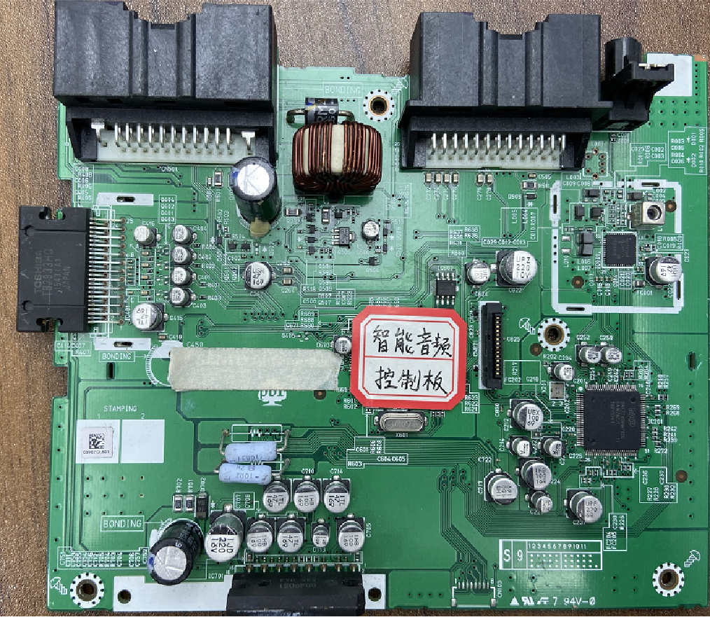
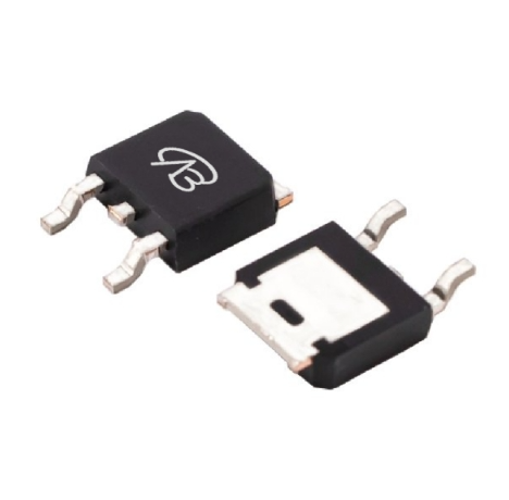
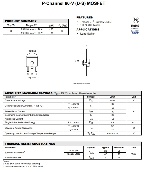
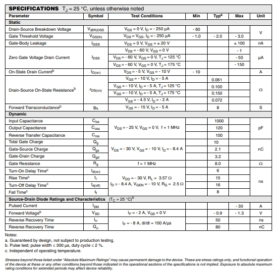
 In order to make the sweeping robot really play a role, intelligent control and efficient driving are very important. In the design and application of the sweeping robot (EV) vacuum cleaner, the selection of the right MOSFET is the key. As one of the core components of the sweeping robot vacuum cleaner, the performance of MOSFET directly affects the charging efficiency, system stability and the long life of the equipment. Our MOSFET product, VBE2610N- -VB-semi, is widely used in this scheme because of its low on resistance and high threshold voltage, high efficiency and high reliability. It provides stable and reliable power support for these components, ensures the efficient operation of the robot in a variety of complex environments, and improves the cleaning effect and intelligence level. 1. Power management system: As a kind of intelligent home appliance, the sweeping robot contains a complex circuit system inside, among which the power management module is very important. MOSFET Can be used as the core element of the regulator in the power switch module, VBE2610N high performance and low on resistance characteristics make it very suitable for the sweeping robot and vacuum cleaner power management module, through the accurate control of the current and voltage, to achieve the stable output of the circuit. It can provide efficient electricity conversion and stable current output, thus extending the battery use time and improving the overall energy efficiency of the equipment. 2. Intelligent control: In the sweeping robot, intelligent control functions such as path planning, automatic obstacle avoidance, intelligent scheduling and so on all need high-precision circuit control. VBE2610N The high reliability and stability make it a key component of these intelligent control functional circuits, which can ensure that the sweeping robot can achieve efficient cleaning and intelligent operation in a variety of complex environments 3.Efficient drive: Sweeping robots are usually equipped with motor drive components such as the main brush and side brush, which require precise current and voltage control to achieve efficient cleaning effect. VBE2610N Has high voltage resistance, can work steadily in high voltage environment, ensure the safety and reliability of electric tools, and reduce the power loss and improve the power density, VBE2610N high current carrying capacity and stable voltage control ability make it the ideal choice in the motor drive circuit, to ensure that the motor under a kinds of load conditions can run operation, provide stable power output. Applications in other areas In the wireless communication equipment power amplifier module: VBE2610N Using trench process manufacturing, with low conduction resistance and high current processing capacity, with high efficiency, high reliability and high current processing capacity, making VBE2610N become one of the indispensable electronic components in wireless communication equipment, help to improve the performance and reliability of the whole system. In the LED lighting drive VBE2610N As an MOSFET suitable for high-power applications, it shows significant advantages in LED lighting drivers. It can not only provide accurate power control, through adjusting the conduction state to adjust the LED light intensity, meet the demand of diversified lighting, also because of its low conduction resistance and achieve high efficiency conversion, reduce power loss, its TO252 packaging form easy to integrate and encapsulation, save space, improve the compactness of lighting system and stable stability and extend the service life. Product Parameter Product model number: VBE2610N Polarity: P channel drain-source voltage (VDS):60V Grid source voltage (VGS): ± 20V Threshold voltage (Vth):1.7V On-on resistance (RDS(on)@VGS=4.5V): 72m Ω On-on resistance (RDS (on) @ VGS = 10 V): 61mΩ Maximum drain current:30A Technology: groove(groove type) Package: SOT 252 VBE2610N MOSFET—VB-semi has the characteristics of low on resistance and high threshold voltage, high efficiency, high reliability, widely used in sweeping robot and vacuum cleaner, can also be used in voltage regulator, power switch module and other fields. Such as the power amplifier module, LED lighting driver in the wireless communication equipment. Its low threshold voltage and large rated leakage electrode current also make it an ideal choice for home appliance control module, industrial motor controller and other fields. VBE2610N Can improve the performance and competitiveness of its products, to bring users a better use experience and more high-quality, efficient and reliable products. #mosfet #semiconductor #automotivebodycontrol #vehicle #headlights #wipers #mirrors #seats #windows


-

Why do MOS tubes need to be connected in parallel with a diode?
ilianaboone replied to vbsemi's topic in Microelectronics
MOSFETs are often connected in parallel with a diode, typically a flyback diode or Schottky diode, to protect the MOSFET from voltage spikes and to ensure proper operation in certain circuits, especially in inductive load applications. Inductive Loads: When a MOSFET is used to switch an inductive load (such as a motor or relay), the inductance of the load generates a high voltage spike (back EMF) when the MOSFET turns off. This spike can exceed the MOSFET's voltage rating and potentially damage it. The diode provides a path for the current to safely dissipate, preventing the MOSFET from experiencing excessive voltage. Body Diode of MOSFET: MOSFETs have an intrinsic body diode (built-in diode between drain and source), but in some applications, this diode may not provide adequate protection or may be slow to respond. Adding an external diode can improve performance, reduce losses, and ensure faster response time. Flyback Diode for Switching Circuits: In circuits like DC-DC converters, the diode helps manage the energy stored in the inductor during switching, improving efficiency and ensuring stable operation. click here:Introduction to the basics of MOSFET -
Request a Free Sample and Experience Our Superior Quality! ✔Valid indefinitely ✔Limited Stock :ONLY 200 pieces https://www.cdebyte.com/resources-FreeTrial
-
To find a comprehensive Network Configuration Guide for Routers based on the NXP 104x platform, there are a few key sources you can explore, which should provide you with all the information you need for setting up and configuring the router: 1. NXP Official Documentation: NXP provides detailed documentation on their platforms, including configuration guides, reference manuals, and datasheets. For the NXP 104x platform, you'll want to check the following: NXP 104x Processor Reference Manual: This will contain detailed information about the hardware architecture, communication interfaces, and configuration options. SDK (Software Development Kit): NXP often provides SDKs that include network stack implementations, drivers, and configuration examples specifically for their platforms. User Guides and Application Notes: These often contain step-by-step instructions for setting up specific use cases, including networking. You can access these documents on the NXP website. Search for the NXP 104x processor, which is based on the i.MX family of SoCs, and look under the documentation and support sections. 2. NXP Community and Forums: NXP has an online community where engineers discuss hardware and software setups for various platforms. You can search for NXP 104x network configurations or ask specific questions about the router setup. NXP Community: community.nxp.com Embedded Software Forum: You might find topics specific to network configurations for routers or similar setups.
-
I want to build an electronic circuit
ilianaboone replied to Witain's topic in Electronic Projects Design/Ideas
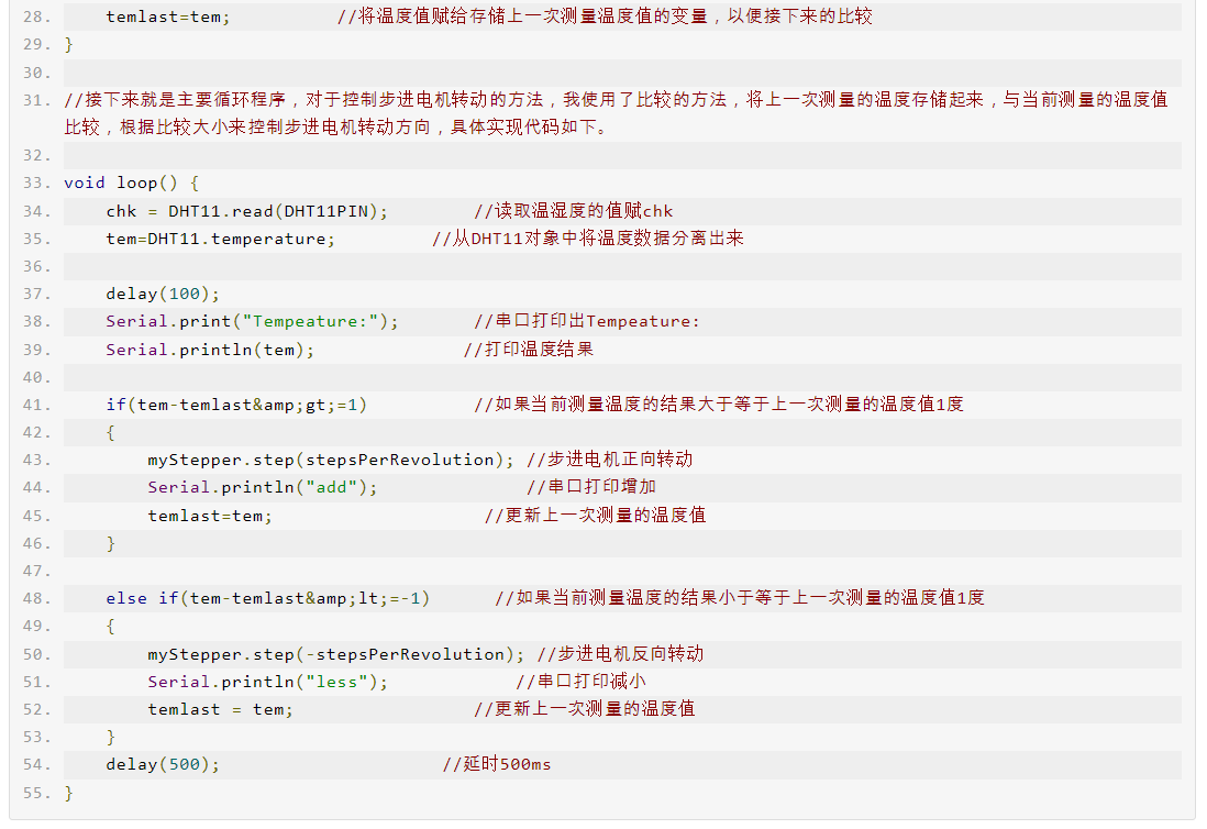
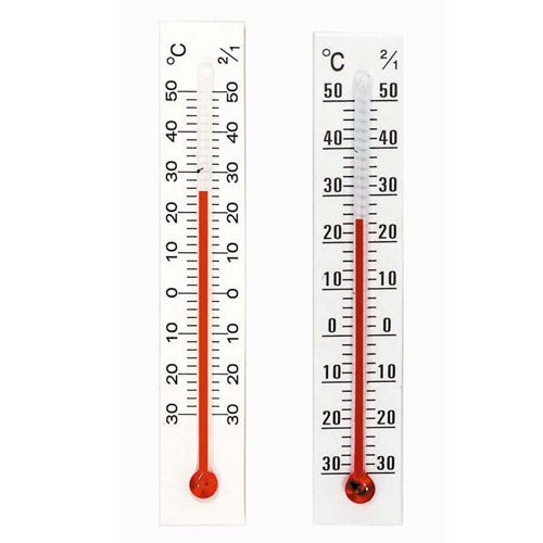
Yes, it's definitely possible to create a circuit to convert the NTC thermistor's resistance into a corresponding output voltage that drives a DC fan without relying on PWM, and without using microcontrollers or complex software. -
Bluetooth AOA (Angle of Arrival) is a positioning technology in Bluetooth technology, commonly used for indoor positioning and precision tracking applications. It is very different from GPS (Global Positioning System), mainly in terms of its working principle, application scenarios and positioning accuracy. What is Bluetooth AOA (Angle of Arrival)? Bluetooth AOA is a technology that achieves location positioning by calculating the angle at which Bluetooth signals arrive at the receiving device. It usually relies on multiple antenna arrays (such as multiple antennas on the receiving device) to determine the direction of the signal source by measuring the difference in signal arrival time, thereby determining the relative position of the device. Difference from GPS: Working principle: GPS: GPS uses satellite signals to determine the location of the device. GPS devices determine their exact position in three-dimensional space (longitude, latitude and altitude) by calculating the distance to at least four satellites. Bluetooth AOA: AOA relies on a multi-antenna array to receive signals from Bluetooth devices and infers the relative position of the device by the angle of arrival of the signal. It does not rely on satellite signals, but is based on the relative position relationship between devices. Positioning accuracy: GPS: GPS can usually provide meter-level or even centimeter-level accuracy, but this accuracy will drop significantly indoors or where the signal is blocked. Bluetooth AOA: AOA's positioning accuracy is usually higher than GPS, especially in indoor environments. It can provide sub-meter or even higher accuracy, suitable for application scenarios that require precise positioning, such as indoor navigation and asset tracking. Applicable environment: GPS: GPS needs to communicate with at least four satellites, so it is suitable for open outdoor environments, especially where there are no buildings blocking it. Bluetooth AOA: AOA does not rely on satellite signals and is suitable for indoor environments, especially in crowded places or complex buildings where GPS signals are difficult to receive.
-

New Proteus Libraries for Engineering Students
briggpaul59 replied to teprojects1's topic in Electronic Resources
Over recent years, the healthcare industry has undergone a huge digital transformation due to the need to completely update its existing infrastructure. The pandemic and other factors — one of which is an increased desire for patients to take an active role in their own healthcare process — have accelerated the transition of offline medical services to digital, resulting in the need for secure, interoperable, and compliant software solutions. This is the perfect time for the healthcare tech industry, as there has never been such high demand for quality products as there is today. https://gloriumtech.com/healthcare-software-development-and-solutions/ -

Problem with my power amplifier Oberton B1200
finley97544d replied to HackoBoy's topic in Projects Q/A
Great -
In this tutorial, we'll walk you through integrating **LoRa Wio E5** (a low-power, long-range LoRa module) with the **XIAO ESP32-S3** (a compact microcontroller with built-in WiFi and Bluetooth) using **MicroPython**. The goal is to establish LoRa communication between the devices, allowing you to create IoT applications with long-range, low-power data transfer capabilities. 📦 Prerequisites 🛠️ Hardware: 🛰️ Wio LoRa-E5 Module(STM32-based LoRa module) 🖥️ XIAO ESP32-S3 (compact ESP32 board) 🔗 Jumper wires for connecting the modules 📏 Breadboard for prototyping 🔌 USB Cables for flashing and power 🖥️ Software: Python 3.x installed on your PC for firmware flashing and serial communication Thonny IDE (or any MicroPython IDE of your choice) esptool (for flashing MicroPython firmware onto the ESP32-S3) MicroPython firmware for XIAO ESP32-S3 from [MicroPython.org](https://micropython.org/download/esp32/) UART AT command reference for Wio-E5 from Seeed Studio Get PCBs for Your Projects Manufactured You must check out PCBWAY for ordering PCBs online for cheap! You get 10 good-quality PCBs manufactured and shipped to your doorstep for cheap. You will also get a discount on shipping on your first order. Upload your Gerber files onto PCBWAY to get them manufactured with good quality and quick turnaround time. PCBWay now could provide a complete product solution, from design to enclosure production. Check out their online Gerber viewer function. With reward points, you can get free stuff from their gift shop. Also, check out this useful blog on PCBWay Plugin for KiCad from here. Using this plugin, you can directly order PCBs in just one click after completing your design in KiCad. 🔧 Step 1: Flashing MicroPython on XIAO ESP32-S3 and Wio LoRa E5 🔥 Flashing MicroPython on XIAO ESP32-S3: 1. Download the MicroPython firmware for ESP32-S3 from (https://micropython.org/download/esp32/). Make sure to download the **ESP32-S3 specific firmware. 2. Install esptool: You'll need the esptool package to flash MicroPython on the ESP32-S3. Install it with: pip install esptool 3. Erase existing firmware on the XIAO ESP32-S3 by connecting it to your PC and running the following command: esptool.py --chip esp32s3 --port <your-port> erase_flash 4. Flash the MicroPython firmware: Replace `<your-port>` with the port the ESP32-S3 is connected to (e.g., `COM4` on Windows or `/dev/ttyUSB0` on Linux). Then, run: esptool.py --chip esp32s3 --port <your-port> write_flash -z 0x1000 esp32s3-<your-firmware>.bin 🚀 Flashing Wio LoRa-E5: The Wio LoRa-E5 module communicates primarily over UART using AT commands. You won't flash MicroPython onto it but will communicate with it through AT commands from the XIAO ESP32-S3. For detailed instructions on setting up the Wio-E5 with firmware, refer to the [Seeed Studio documentation] 🔌 Step 2: Wiring Connections Here’s how you can connect the **XIAO ESP32-S3** to the **Wio LoRa-E5** module using UART: Ensure that you connect the pins correctly, especially the TX and RX, as this will facilitate communication between the devices. 🔧 Step 3: Setting Up Thonny IDE for ESP32-S3 1. Download and install Thonny IDE if you haven't already. 2. Select **ESP32** as your MicroPython interpreter. 3. Plug in your XIAO ESP32-S3, and in Thonny, go to Tools > Options > Interpreter, then select the correct Port corresponding to your device (e.g., `COM3` on Windows or `/dev/ttyUSB0` on Linux). Verify the connection by running: print("Hello from XIAO ESP32-S3!") If the message prints to the terminal, you are connected! 🧑💻 Step 4: Sending AT Commands from XIAO ESP32-S3 to Wio LoRa-E5 To communicate with the Wio LoRa-E5, you will use UART on the XIAO ESP32-S3 to send AT commands. Here’s a basic MicroPython script to initialize UART communication and send commands. MicroPython UART Communication Script: # P2P Transmitter Example from machine import UART, Pin from utime import sleep_ms uart1 = UART(1, baudrate=9600, tx=Pin(43), rx=Pin(44)) def echo(): rxData=bytes() while uart1.any()>0: rxData += uart1.read(1) print(rxData.decode('utf-8')) uart1.write('at+mode=test\n') # enter test mode sleep_ms(100) data = 0 while True: print("Send data:",data) uart1.write('at+test=txlrpkt,"{}"\n'.format(data)) # send test data sleep_ms(100) echo() # show debug data from LoRa-E5 module data += 1 # increment and loop test-data data = data % 255 print("") sleep_ms(1000) This script initializes UART communication on the XIAO ESP32-S3 and sends an AT command to the Wio LoRa-E5. The response is printed to the console. 🛠️ Step 5: Receiving Data on XIAO ESP32-S3 To receive data from the Wio LoRa-E5, you’ll need to listen for incoming messages using UART. The following script listens for LoRa messages: # P2P Receiver Example from machine import UART, Pin from utime import sleep_ms uart1 = UART(1, baudrate=9600, tx=Pin(4), rx=Pin(5)) def echo(): rxData=bytes() while uart1.any()>0: rxData += uart1.read(1) data = rxData.decode('utf-8') out = data.replace('+TEST: RXLRPKT','') print(out) uart1.write('at+mode=test\n') # enter test mode sleep_ms(100) while True: uart1.write('at+test=rxlrpkt\n') echo() # show debug data from LoRa-E5 module sleep_ms(1000) This script puts the Wio-E5 in receive mode and continuously listens for incoming messages. 🧪 Step 6: Testing Your Setup Now that both sending and receiving are set up: 1. Power up both devices. 2. Send a message from one device (e.g., "Hello LoRa!"). 3. Receive the message on the other device. 4. Verify that the message appears correctly on the receiving device's console. You can also monitor communication through Thonny IDE. 📚 Additional Enhancements Add Sensors: Connect environmental sensors (like temperature or humidity) to your XIAO ESP32-S3 to send real-world data over LoRa. Wi-Fi Gateway: Use the Wi-Fi capability of the ESP32-S3 to forward LoRa data to a cloud service like MQTT -Deep Sleep: Implement power-saving techniques by putting the ESP32-S3 in deep sleep mode to save battery life in remote applications. 🎉 Conclusion Congratulations! You've successfully integrated LoRa Wio-E5 with XIAO ESP32-S3 using MicroPython. This project enables you to build a wide range of long-range IoT applications, such as environmental monitoring, smart agriculture, or asset tracking. 🚀 Feel free to extend this project, add sensors, and explore the vast possibilities of LoRa and ESP32-S3.
-
Great
-
Hey! Cool project you’re working on. For TNT SIM cards, if you're looking into registration,we have info on TNT SIM registration numbers and steps for getting started. Best of luck, and feel free to reach out if you have questions!
-
 From your description it sounds like this device is measuring the high voltage at the spark plug terminals and using a neon bulb to reflect that voltage level through a change in light? Slice Master
 - Earlier
-

Automotive AGM Start-Stop Battery vs. Traditional Battery
Sallyschalk replied to camelbatt's topic in Power Electronics
Additionally, eggy car reflecting on essays or articles can further enrich your understanding and appreciation of various topics, leading to a more fulfilling experience overall. -
 Cross-compilation Toolchain Location: OK113i-linux-sdk/out/t113_i/ ok113i/longan/buildroot/host/bin/arm-linux-gnueabihf-gcc Before executing the method below, please delete the out directory and decompress the cross-compilation tool chain in the lower path of the source code./buildroot/buildroot-201902/dl/toolchain-external-linaro-arm/gcc-linaro-7.3.1-2018.05-x86_64_arm-linux-gnueabihf.tar.xz 1. Modify mkcmd.sh and mkcommon.sh according to the patch modification method in the figure. 2. Go back to the sdk path and execute the following command: forlinx@ubuntu:~/shuishui/OK113i-linux-sdk$ ./build.sh config It is modified to emmc or NAND version according to the actual board configuration. 3. Next, execute the following command to enter the configuration of buildroot. Enter toolchain Modify the relevant options as shown in the figure below: Enter target options Because hard-float is needed, the highlighted part in the diagram needs to be modified to EABIhf. Save and exit after setting. Enter the following path to compile. ./build.sh Full compilation may require an error with an environment variable, resulting in a failure to compile. If this problem occurs, execute the following instructions and compile the buildroot. export LD_LIBRARY_PATH="" In the middle of compiling buildroot, you may encounter an error as shown in the following figure. If these errors are encountered, you can find the corresponding source code and compile it through the tools in the decompressed cross-compilation chain. Subsequently, place the compiled executable file in the bin path and the library file in the lib path. Finally, continue executing ./build.sh until compilation is successful. After compiling successfully, return to the SDK path, perform full compilation build. sh, and then pack the image. Next, write a test program to verify whether the cross-compilation chain can be successfully replaced. Here, you need to compare the program compiled with the original compilation chain with the program cross-compiled with the current compilation chain. The part highlighted in the diagram is a program compiled using our original cross-compilation chain. It can be observed that it does not run normally. "Test" is a program compiled using the tools from the replaced cross-compilation chain, which runs normally. Additionally, the relevant information of the two programs can be determined using the ''strings'' tool.

-
 We can help design this
 -
I want to build an electronic circuit
Steven Ramos replied to Witain's topic in Electronic Projects Design/Ideas
Can you give me a call? -
A new source
-

Automotive AGM Start-Stop Battery vs. Traditional Battery
AngelGutkowski replied to camelbatt's topic in Power Electronics
As far as I know, AGM batteries use an absorbent glass mat instead of liquid electrolyte like regular lead-acid batteries. This may be a small difference. fall guys